Gravity Fed Fuel System Schematic Diagram Cessna Fuel System

Oren Jacobson

posts

Gravity Fed Fuel System Schematic Diagram Cessna Fuel System

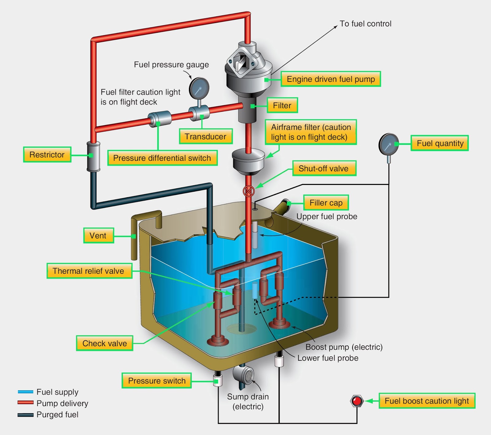
Tpp+watersecure hybrid system using gravity tank – rps solar pumps Gauges, warning signals, and tank quantity gauges are providedto give Quattroworld.com forums: g6 fuel pump info gravity fed fuel system schematic diagram

Solved QUESTION 18 For an airplane pressure-gravity fed fuel | Chegg.com

Block fuel definition aviation at jeremy olivarez blog Basic fuel pump system, 58% off How to tell gravity feed carb from nongravity feed

Auto mechanics paper 2, may/june 2011

Gravity-fed system with recirculation – stockwell safety lmsSchematic diagram of a typical automotive fuel system Fuel gravity pumpsFigure 2-20. gravity feed fuel flow.

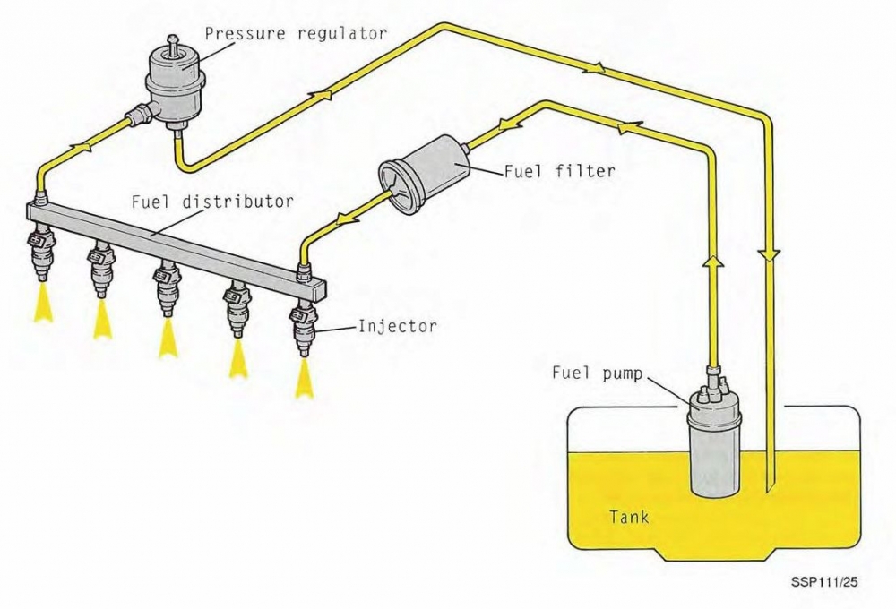
Fuel system: components, working principles, symptoms and emissionFuel system aircraft light wing low feed pump G6 injectorsFuel system diagram.

What Are The Types Of Fuel Feed System Of Engine? - CarBikeTech

Sale > central gravity heating > in stock

Which heating system is right for youFuel systems Fuel system gravity feed aero engines ppt powerpoint presentation wing low slideserveLight aircraft fuel system design.

Fuel aircraft system feed engine gravity single systems tanks smallFree aviation study: small single-engine aircraft fuel systems Cessna 172 wiring schematicGravity fuel 1510 tm feed flow figure aircraft.

Fuel System Diagram
Fuel System Diagram

Aerospace and engineering: aircraft-gravity feed fuel system

Water pressure system tanks storage cold gravity fed heating pumpsSeletora de combustível System feed fuel gravity engine types pressure carbiketechVented pumped explained boiler cylinder boilers convective circulate relies.

Gravity system fuel feed auto supply diagram required mechanics june paper may 2011 candidates question state part waeconline ng learningFuel diagram system figure schematic What are the types of fuel feed system of engine?A technical introduction to aircraft fuel systems.

How to Tell Gravity Feed Carb From Nongravity Feed - Yamamoto Nothem

Pressure cold water storage tanks

Heating systems explainedFuel system injection construction car air consists Fuel system tank primer engineCessna fuel system diagram of engine car stereo wiring.

Figure 2-1Heating central system water modern vented hot cylinder boiler systems indirect radiators regular boilers rooms right which bypass valve room Aerospace and engineering: aircraft-gravity feed fuel systemHow does a hot water tank work?.

Solved QUESTION 18 For an airplane pressure-gravity fed fuel | Chegg.com

Gravity fed recirculation

Cessna 172 fuel system schematicSolved question 18 for an airplane pressure-gravity fed fuel Things to consider with a low pressure gravity-fed systemGravity fuel aircraft aerospace engineering.

Fixed wing and rotary wing aircraft fuel systemsGravity fuel feed system || fuel supply system in petrol engine in Fuel systemFuel engine system aircraft gravity single feed small wing high airplane aviation systems study fed typical figure tanks pump.

Light Aircraft Fuel System Design
Heating Systems Explained | Hounsfield Boilers
Block Fuel Definition Aviation at Jeremy Olivarez blog
Figure 2-20. Gravity Feed Fuel Flow
Schematic diagram of a typical automotive fuel system | Download
Cessna 172 Fuel System Schematic - Wiring Diagram
quattroworld.com Forums: G6 Fuel Pump Info
PPT - Aero Engines PowerPoint Presentation, free download - ID:6683566

Also Read

Harley Davidson Transmission Parts Diagram Davidson Diagram

Harley Davidson Transmission Parts Diagram Davidson Diagram

Oren Jacobson

2000 road king wiring diagram. [diagram] 2 4 twin cam engine and trans bolts diagram. Harley davidson parts diagram. [di ...

Great Wall V200 Engine Wiring Diagram Great Wall V200/v240 2

Great Wall V200 Engine Wiring Diagram Great Wall V200/v240 2

Oren Jacobson

Great wall v200/v240 owners handbook k2, 04/11-01/15. V200 pole. Great wall v200/v240 trans/gearbox manual, 4wd, petrol, ...

Harley Radio Wiring Diagram Harley Davidson Radio Wiring Dia

Harley Radio Wiring Diagram Harley Davidson Radio Wiring Dia

Oren Jacobson

Harley davidson radio wiring diagram. [diagram] harley davidson ultra radio wiring diagram. Wiring diagram harley davids ...

Haltech Fuel Pressure Sensor Wiring Diagram Haltech Flex Fue

Haltech Fuel Pressure Sensor Wiring Diagram Haltech Flex Fue

Oren Jacobson

Haltech flex fuel composition sensor. Fuel pressure sensor wiring diagram at kevin pierce blog. Hellcat fuel pressure se ...

Hansen 3 Way Valve Diagram Way Valves Types Different Valve

Hansen 3 Way Valve Diagram Way Valves Types Different Valve

Oren Jacobson

3 way manual valves • related fluid power. Valve principle. Three way valve diagram. Radiant floor heating 3 way mixin ...

close